
 Installation Reports
1. Measurement Details
- Measurement Date
April 18, 2020 - Measurement Devices
1. LAN-XI Data Acquisition Hardware
– Brüel & Kjæ r 3050-B-040
2. Data Analysis Software
– Brüel & Kjæ r PULSE LAB SHOP 14
3. Sensors
– PCB Accelerometer
– Model: 393B05 - Measurement Location
Ground Floor
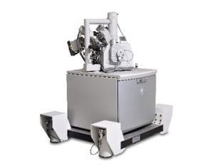
2. Equipment Information
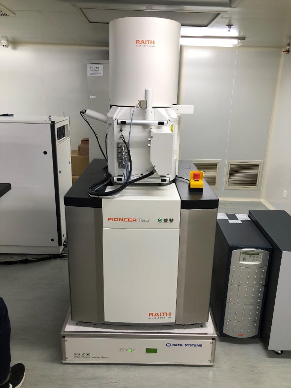
- Manufacturer
RAITH - Model
PIONEER Two Electron Beam Lithography & SEM - Floor Vibration Specification
The velocity of floor vibrations measured in a 1/3-octave RMS amplitude spectrum has
to be less than 1.0 μm/sec for frequencies between the 1.6-Hz band and the 10-Hz band
(including them). For frequencies above the 10-Hz band the maximum velocity should
not exceed 2.0 μm/sec. (A similar result can be achieved, if the floor vibrations are less
than the specifications defined by the standard NIST-A.)
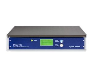
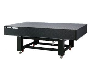
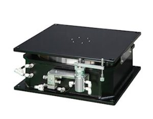
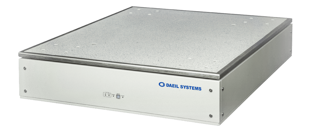
3. Vibration Isolation System Information
Model: DVIA-MB1000
| Platform Dimensions | 1140 x 910 x 224 mm | |
| Load Capacity | 500 - 1700 kg | |
| Actuator | Electromagnetic Actuator | |
| Maximum Actuator Force | Vertical: 40N, Horizontal: 20 N | |
| Degrees of Freedom | 6 degrees | |
| Active Isolation Range | 0.5 - 100 Hz | |
| Vibration Isolation at 2 Hz | ≥90% | |
| Vibration Isolation at 10 Hz | ≥99% | |
| Input Voltage (V) | AC100 - 240V / 50 - 60 Hz / 1A | |
| Power Consumption (W) | Maximum 110W, <50 W in normal operation | |
| Operating Range | Temperature (°C) | 5 - 50 °C |
| Humidity (%) | 20 - 90% | |
| Required Air Pressure | ≥ 0.5 MPa (5 bar) | |
4. Installation Photos
5. Summary
| Vibration Criterion Curves | ||||||
|---|---|---|---|---|---|---|
| Frequency Range | 1-10 Hz | 10 - 80 Hz | ||||
| Measurement Direction | Z axis (Vertical) | X axis (Left to Right) | Y axis (Front to Back) | Z axis (Vertical) | X axis (Left to Right) | Y axis (Front to Back) |
| Floor | VC-B (Fail) | VC-D (Fail) | VC-D (Fail) | VC-C (Fail) | VC-E (Fail) | VC-F (Pass) |
| On Active Vibration Isolation System | VC-G (Pass) | VC-G (Pass) | VC-E (Pass) | VC-E (Pass) | VC-G (Pass) | VC-G (Pass) |
The floor vibration specification of the RAITH Pioneer Two is extremely challenging, the measured floor vibrations did not meet the vibration specification. DAEIL SYSTEMS’s active vibration isolation system reduced the floor vibration in Z, X and Y axis, achieved to meet the vibration specification.
6. Results
Z-axis (Vertical)
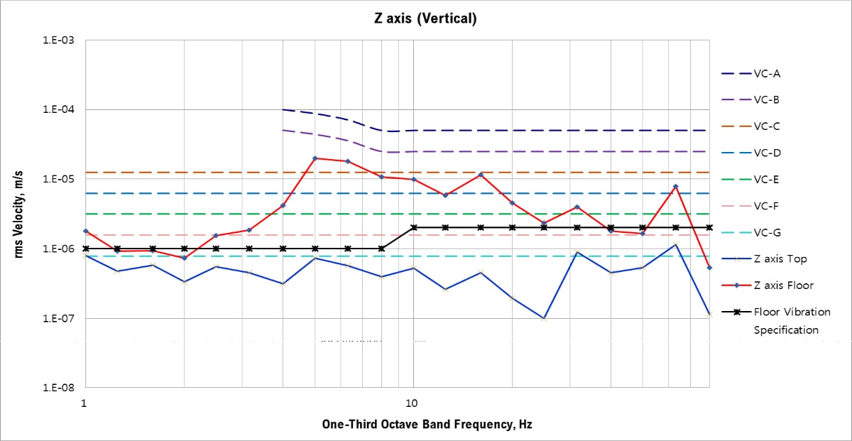
AVI = Active Vibration Isolation
The measured vertical floor vibration exceeded the allowable floor vibration values from 1 to 80 Hz.
After the installation of DAEIL SYSTEMS’s active vibration isolation system, the floor vibrations were reduced to meet the floor vibration specification.
X-axis (Left to Right)
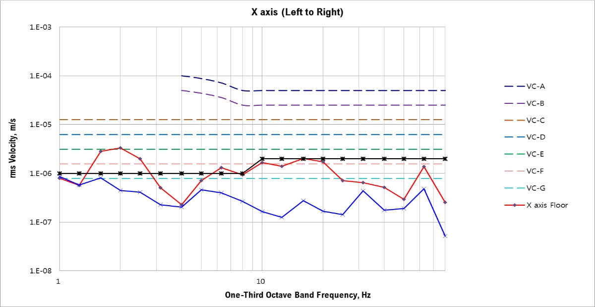
AVI = Active Vibration Isolation
The measured floor vibration in X axis below 10 Hz exceeded the allowable floor vibration. DAEIL SYSTEMS’s active vibration isolation system reduced the floor vibration from VC-E to VC-G in 1 – 80 Hz, meeting the floor vibration specification.
Y-axis (Front to Back)
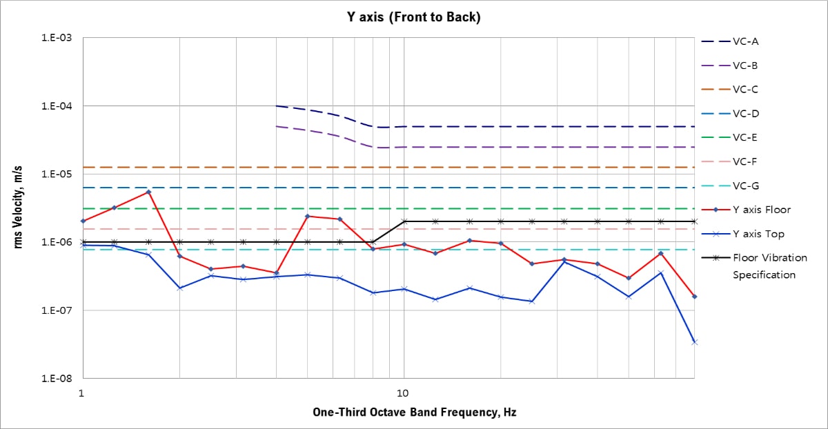
AVI = Active Vibration Isolation
The low frequency floor vibration at 1.6 Hz, 5 Hz, 6.3 Hz exceed the allowable floor vibration values.
DAEIL SYSTEMS’s active vibration isolation system reduced these vibrations, achieved to meet the floor vibration specification
7. Reference
Generic Vibration Criteria
| Criterion Curve | Description | Amplitude1) μm/s (in/s) | Detail Size2) μm |
|---|---|---|---|
| Workshop (ISO) | Distinctly perceptible vibration, Appropriate to workshops and non-sensitive areas. | 800 (32,000) | N/A |
| Office (ISO) | Perceptible vibration. Appropriate to offices and non-sensitive areas. | 400 (16,000) | N/A |
| Residential Area (ISO) | Barely perceptible vibration. Appropriate to sleep areas in most instances. Usually adequate for computer equipment, hospital recovery rooms, semiconductor probe test equipment, and microscopes less than 40x. | 200 (8,000) | 75 |
| Operating Theatre (ISO) | Vibration not perceptible. Suitable in most instances for surgical suites, microscopes to 100x and for other equipment of low sensitivity. | 100 (4,000) | 25 |
| VC-A | Adequate in most instances for optical microscopes to 400x, microbalances, optical balances, proximity and projection aligners, etc. | 50 (2,000) | 8 |
| VC-B | Appropriate for inspection and lithography equipment (including steppers) to 3pm line widths. | 25 (1,000) | 3 |
| VC-C | Appropriate standard for optical microscopes to 1000x, lithography and inspection equipment (including moderately sensitive electron microscopes) to 1μm detail size, TFT-LCD stepper/scanner processes. | 12.5 (500) | 1-3 |
| VC-D | Suitable in most instances for demanding equipment, including many electron microscopes (SEMs and TEMs) and E-Beam systems. | 6.25 (250) | 0.1-0.3 |
| VC-E | A challenging criterion to achieve. Assumed to be adequate for the most demanding of sensitive systems including long path, laser-based, small target systems, E-Beam lithography systems working at nanometer scales, and other systems requiring extraordinary dynamic stability. | 3.12 (125) | <0.1 |
| VC-F | Appropriate for extremely quite research spaces; generally difficult to achieve in most instances, especially cleanrooms. Not recommended for use as a design criterion, only for evaluation. | 1.56(62.5) | N/A |
| VC-G | Appropriate for extremely quite research spaces; generally difficult to achieve in most instances, especially cleanrooms. Not recommended for use as a design criterion, only for evaluation. | 0.78(31.3) | N/A |
- As measured in one-third octave bands of frequency over the frequency 8 to 80 Hz (VC-A and VC-B) or 1 to 80 Hz (VC-C through VC-G).
- The detail size refers to line width in the case of microelectronics fabrication, the particle (cell) size in the case of medical and pharmaceutical research, etc, It is not relevant to imaging associated with probe technologies, AFMs, and nanotechnology.
The information given in this table is for guidance only. In most instances, it is recommended that the advice of someone knowledgeable about applications and vibration requirements of the equipment and processes be sought.