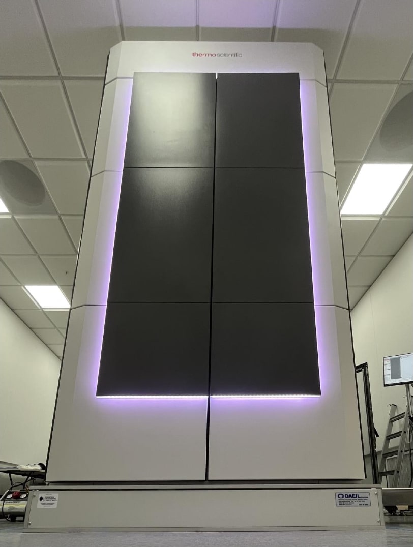
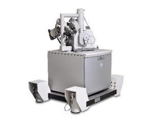
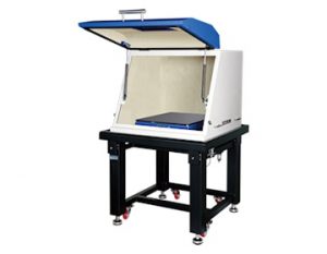
The purpose of this work is to install the Vibration Isolation MB3000 system for the Thermo Fisher Scientific Spectra 200 in , Spectra Room.
Summary Results
Below is a summary of the results:
MB3000 ON PASSED the Vibration specifications
• Introduction
The purpose of this work is to install the Vibration Isolation MB3000 system for the Thermo Fisher Scientific Spectra 200 in , Spectra Room.
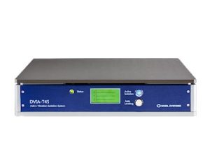
• Product Details
Part Delivered
Serial Number
Software
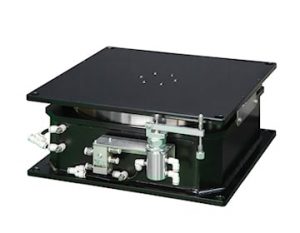
MB3000
220542R2
Site-Specific Tune
• Summary of Work
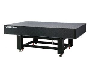
We installed the system by
Leveling the daeil to within .5mm
Connecting the seismic restrains between the daeil and the tool
We tested the system by
Collecting vibration data to verify the performance
We left the system
In position and off
• Installer's Notes
• Procedures
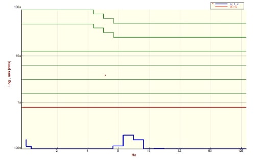
Vibration
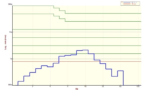
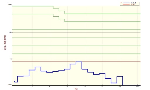
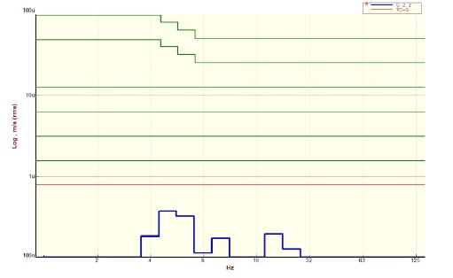
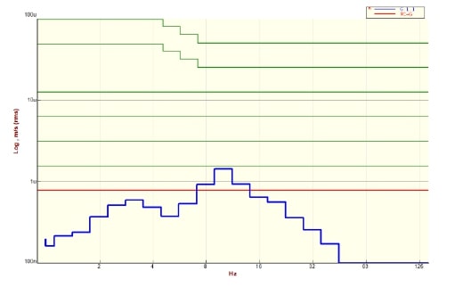
VEC conducted vibration measurements in six directions. Acceleration measurements were taken at a bandwidth of 200 with units of m/s (RMS). The acceleration spectra with 200 bandwidths were recorded.
• Setup
Vibration
Bandwidth
200
Lines
3200
Window
Hanning
Coupling
ICP 2mA
Average Type
Stable
Duration
60
Engineering Units
um/s (RMS)
• Specifications
VEC used the following specifications for the project.
 Installation Reports